Hardware Configuration
1. RBgrid Controller Overview
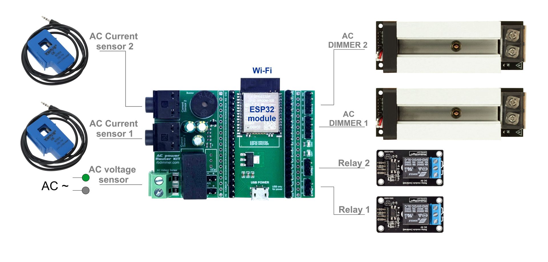
The RBgrid controller is a complete solution for electrical power measurement with integrated components on a single board.
Built-in Components
Main Measurement Components
- Microcontroller: ESP32-WROOM-32E (dual-core, 240 MHz)
- Voltage Sensor: ZMPT107-1 on GPIO35 (onboard, galvanically isolated from AC mains)
- Current Sensor Inputs: 2 × 3.5mm Jack sockets
- Channel 1: GPIO36 (ADC1_CH0)
- Channel 2: GPIO39 (ADC1_CH3)
- Compatible with all SCT-013 variants
Additional Interfaces
Load Control
- Relay Outputs: 2 channels
- Relay 1: GPIO15
- Relay 2: GPIO02
-
Logic level: 3.3V (requires relay driver)
-
Dimmer Interface: RBdimmer module connection
- Dimmer 1: GPIO15
- Dimmer 2: GPIO02
- Zero-Cross: GPIO18 (shared for all dimmers)
Indication and Signaling
- Buzzer: GPIO4 (audible event alerts)
- LED1: GPIO17 (status indicator)
- LED2: GPIO5 (activity indicator)
- Additional current sensors (ACS712, INA219)
- I2C devices (displays, port expanders)
- SPI devices (Flash/EEPROM memory, SD cards, external ADCs)
- UART devices (RS485, modems)
2. Connection Diagram
Mains Connection
     Circuit Breaker
          │
    ┌─────┴─────┐
    │     L     │ Live ───────→ [L] ZMPT107-1 on board
    │           │
    │     N     │ Neutral ────→ [N] ZMPT107-1 on board
    └───────────┘
- Perform all work with power disconnected
- Use insulated tools
- Verify absence of voltage with a tester
SCT-013 Current Sensor Connection
- Installation on Wire:
- Open the SCT-013 sensor clamp
- Clamp around ONLY the live wire (L)
- Arrow on sensor should point toward the load
-
Close clamp until it clicks
-
Connection to Controller:
```
SCT-013 → 3.5mm Jack → Socket on board
Channel 1 (GPIO36): Main supply or large load
Channel 2 (GPIO39): Additional load
```
ACS712 Additional Sensor Connection
For ACS712 sensors, use available GPIO pins:
ACS712 Module     →  RBgrid Controller
─────────────────────────────────────
VCC (5V)          →  5V pin
GND               →  GND
OUT               →  GPIO32/33/34 (free ADC1 pins)
3. Controller Power Supply
Main Requirements
- Voltage: 5V DC
- Current: minimum 500mA (1A recommended)
- Stability: ±5% for accurate measurements
Power Connection Options
- Via Micro-USB Port:
- Use quality 5V/1A USB adapter
-
Suitable for testing and debugging
-
Via Power Pins:
- 5V → 5V pin on board
- GND → GND pin on board
- Recommended for permanent installation
- Inaccurate measurements (reading drift)
- False Zero-Cross triggers
- Controller resets
Use linear regulators or quality switching power supplies with filtering.
4. First Power-Up
Pre-Power Checklist
Power-Up Sequence
- Apply 5V Power to Controller
- LED1 should flash at startup
-
Wait 3-5 seconds for initialization
-
Turn ON AC Circuit Breaker
- Controller will start measurements automatically
-
LED2 will blink with measurement frequency
-
Check Operation via Serial Monitor
Connection: 115200 baud, 8N1
   Expected output:
   [RBgrid] System initialized
   [RBgrid] Voltage: 220.5V, Frequency: 50.02Hz
5. Advanced Connections
Relay Connection for Load Control
RBgrid        Relay Module
─────────────────────────
GPIO15    →   IN1
GPIO02    →   IN2
5V        →   VCC (if 5V compatible)
GND       →   GND
RBdimmer Connection
RBgrid        RBdimmer Module
──────────────────────────────
GPIO18    →   Pin 3 (Zero-Cross)
GPIO15    →   Pin 4 (PWM Dimmer 1)
GPIO02    →   Pin 4 (PWM Dimmer 2)
GND       →   GND
6. Common Issues and Solutions
| Problem | Possible Cause | Solution |
|---|---|---|
| No voltage reading | Phase not connected to ZMPT107-1 | Check L and N connections |
| Zero current reading | Sensor on neutral wire | Move to live wire |
| Unstable readings | Poor controller power supply | Use stabilized PSU |
| Negative power | Current sensor reversed | Rotate sensor 180° |
| No Serial communication | Wrong baud rate | Set to 115200 baud |
7. Safety Precautions
- Always disconnect power before changing connections
- Use RCD (Residual Current Device) for additional protection
- Never work with electricity alone
- When in doubt, consult a qualified electrician
Recommended Safety Equipment
- Insulated tools (screwdrivers, pliers)
- Voltage tester
- Dielectric gloves
- Safety glasses
- Rubber mat
8. Conclusion
The RBgrid controller provides everything needed to build a power monitoring system. Built-in components and connectors simplify connection, while exposed GPIO pins allow functionality expansion as needed.