Units Configuration Page
Overview
The Units Configuration page manages electrical measurement points in your RBgrid system. Units are logical abstractions representing different electrical components - from main supply connections to individual loads. Each unit combines a physical sensor with metadata, role definition, and statistical tracking to provide comprehensive energy monitoring.
Units Abstraction Concept
What are Units?
Units are measurement entities that represent specific electrical points in your system. Each unit:
- Links to a physical sensor (current or voltage)
- Has a defined role in the electrical system
- Maintains its own statistics and history
- Provides real-time measurements
- Calculates costs or revenue based on energy flow
Unit Categories
The system supports three categories of units:
- System Units (Special units with predefined roles)
- Voltage Bus - Primary voltage reference
- Main Supply - Grid connection point
- Alternative Supply - Internal generation
- Load Units (Regular consumers)
- Individual devices or zones
- Configurable roles and statistics
- Multiple units allowed
Special System Units
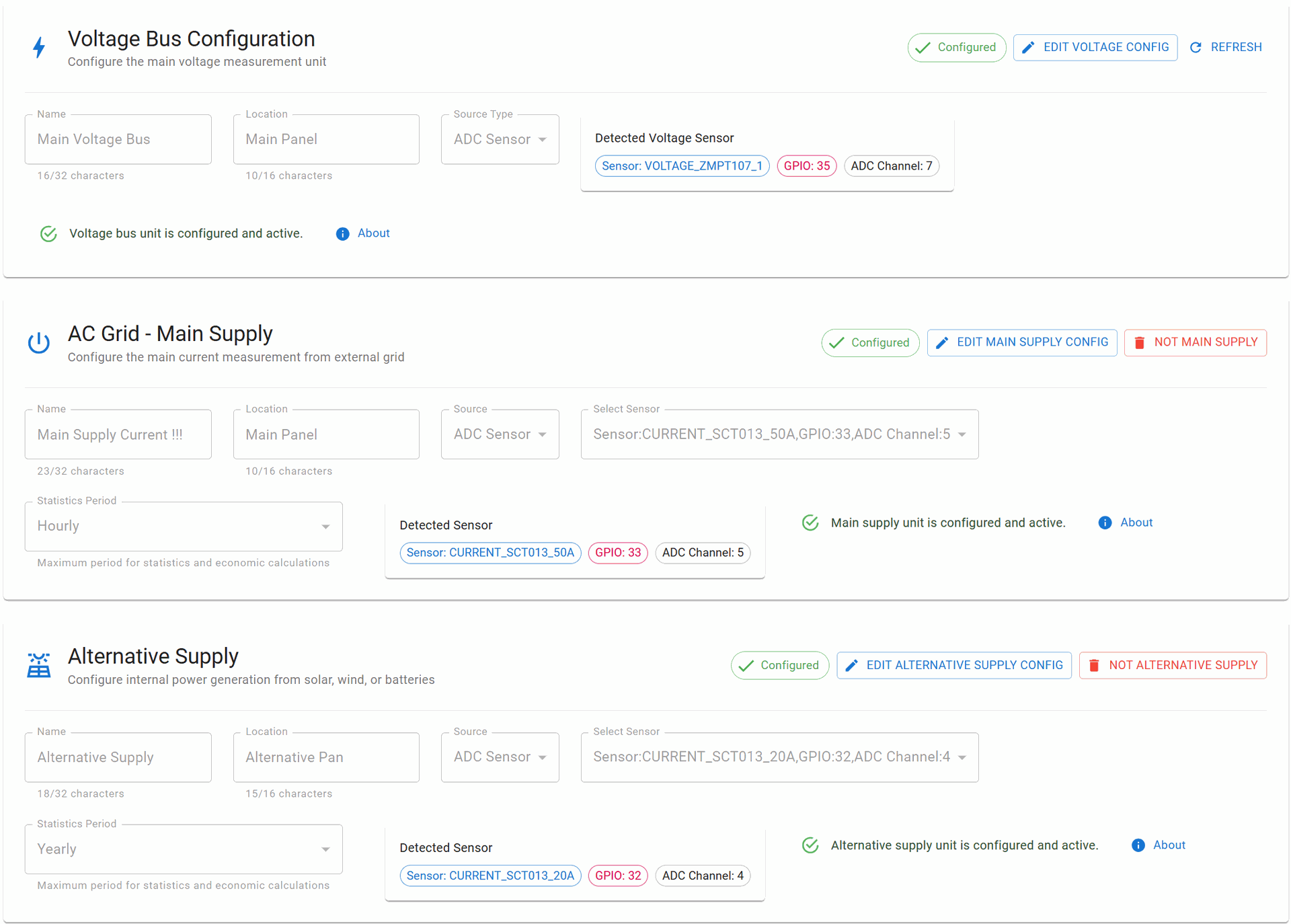
Voltage Bus Configuration
Purpose: Primary voltage measurement reference for the entire system
Key Characteristics:
- Unique: Only ONE Voltage Bus allowed per system
- Required: Essential for power calculations
- No Statistics: Does not store historical data (real-time only)
- Fixed Sensor: Must use voltage sensor type (ZMPT107-1 or ZMPT101B)
Configuration Parameters:
- Name - Descriptive identifier (max 32 characters)
- Location - Physical location (max 16 characters)
- Source Type - Fixed to ADC_SENSOR
- GPIO Pin - Typically GPIO 35 for voltage measurement
Functionality:
- Provides voltage reference for all power calculations
- Enables accurate RMS voltage measurements
- Synchronizes with zero-cross detection
- Real-time monitoring without historical storage
AC Grid - Main Supply
Purpose: Monitors the connection point to the external electrical grid
Key Characteristics:
- Unique: Only ONE Main Supply allowed per system
- Bidirectional: Supports both consumption and feed-in
- Economic Tracking: Calculates costs and revenue
- Statistical Data: Maintains historical consumption/generation data
Configuration Parameters:
- Name - Descriptive identifier (max 32 characters)
- Location - Physical location (max 16 characters)
- Source Type - ADC_SENSOR, I2C, SPI, or ESP-NOW
- Sensor Selection - Current sensor from configured hardware
- Statistics Period - Data aggregation period (see Statistics section)
Functionality:
- Import Monitoring: Tracks energy consumed from grid
- Export Monitoring: Tracks energy fed back to grid (solar/battery)
- Cost Calculation: Applies tariffs to consumption
- Revenue Tracking: Calculates feed-in tariff earnings
- Peak Demand: Records maximum power draw
- Power Quality: Monitors power factor and harmonics
Actions:
- EDIT MAIN SUPPLY - Modify configuration
- NO MAIN SUPPLY - Remove special status (converts to regular unit)
Alternative Supply
Purpose: Monitors internal power generation sources (solar, wind, batteries)
Key Characteristics:
- Unique: Only ONE Alternative Supply allowed per system
- Bidirectional: Tracks generation and charging cycles
- Self-Consumption: Monitors direct usage of generated power
- Economic Analysis: Calculates savings and ROI
Configuration Parameters:
- Name - Descriptive identifier (max 32 characters)
- Location - Physical location (max 16 characters)
- Source Type - ADC_SENSOR, I2C, SPI, or ESP-NOW
- Sensor Selection - Current sensor from configured hardware
- Statistics Period - Data aggregation period
Functionality:
- Generation Tracking: Real-time and cumulative generation
- Charge Monitoring: Battery charging power and efficiency
- Self-Consumption Rate: Percentage of generated power used locally
- Grid Independence: Calculate off-grid operation time
- Environmental Impact: CO₂ savings calculations
Actions:
- EDIT ALT SUPPLY - Modify configuration
- NO ALT SUPPLY - Remove special status (converts to regular unit)
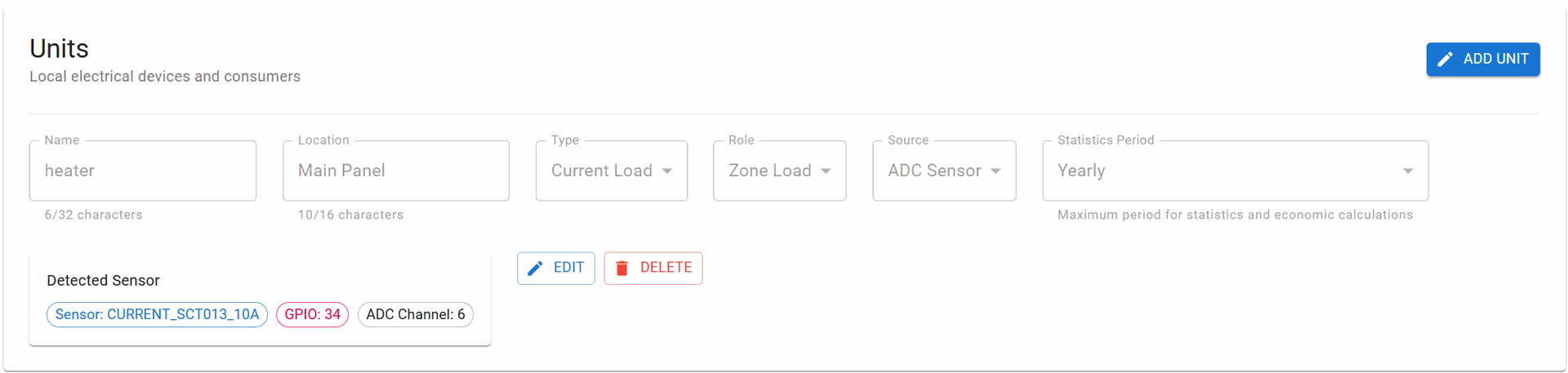
Regular Units (Loads)
Purpose: Monitor individual electrical consumers, zones, or circuits
Key Characteristics:
- Multiple Units: Unlimited number of regular units
- Flexible Roles: Can be configured for different purposes
- Individual Statistics: Each unit maintains its own data
- Grouping Support: Can be organized by location or type
Configuration Parameters:
- Name - Device or circuit name (max 32 characters)
- Location - Installation location (max 16 characters)
- Type - CURRENT_LOAD, VOLTAGE_MONITOR, or POWER_METER
- Role - Functional role in the system:
- ZONE_LOAD - Area or room circuit
- DEVICE_LOAD - Specific appliance
- CRITICAL_LOAD - Essential equipment
- HVAC_LOAD - Heating/cooling systems
- LIGHTING_LOAD - Lighting circuits
- Source Type - ADC_SENSOR, I2C, SPI, or ESP-NOW
- Sensor Selection - Any available sensor
- Statistics Period - Data aggregation period
Actions per Unit:
- EDIT - Modify unit configuration
- DELETE - Remove unit from system
- ADD UNIT - Create new measurement unit
Statistics Period Configuration
What is Statistics Period?
The Statistics Period defines how long historical data is stored and the granularity of data aggregation. It determines:
- Memory allocation for historical data
- Resolution of stored measurements
- Available time ranges for analysis
- Storage optimization strategy
Available Periods
Details on Tariffs seting page
Data Stored in Statistics
For each configured period, the system maintains:
Energy Metrics:
- Total consumption (kWh)
- Peak demand (kW)
- Average power (W)
- Minimum power (W)
- Power factor (cosφ)
Economic Data:
- Total cost/revenue
- Tariff periods applied
- Peak vs off-peak consumption
- Cost per kWh trends
Quality Metrics:
- Voltage variations
- Frequency deviations
- THD (Total Harmonic Distortion)
- Interruption events
Aggregated Values:
- Hourly summaries
- Daily profiles
- Monthly totals
- Yearly comparisons
Memory Management
Storage Allocation:
- Each unit allocates memory based on selected period
- Circular buffer implementation (oldest data overwritten)
- Compression for long-term storage
- Backup to external storage supported
Access Methods:
- REST API endpoints for data retrieval
- WebSocket streaming for real-time updates
- CSV/JSON export functionality
- MQTT publishing of summaries
Typical Configuration Examples
Example 1: Residential with Solar
1. Voltage Bus: "Main Panel Voltage" (GPIO 35)
2. Main Supply: "Grid Connection" (100A CT, YEARLY statistics)
3. Alternative Supply: "Solar Inverter" (50A CT, YEARLY statistics)
4. Unit:
   - "Kitchen Circuit" (20A CT, WEEKLY)
Example 2: Small Business
1. Voltage Bus: "Distribution Board" (GPIO 35)
2. Main Supply: "Utility Meter" (100A CT, YEARLY statistics)
3. No Alternative Supply
4. Units:
   - "Office Zone" (50A CT, MONTHLY)
   - "HVAC System" (30A CT, WEEKLY)
Example 3: Off-Grid System
1. Voltage Bus: "Battery Voltage" (GPIO 35)
2. No Main Supply (off-grid)
3. Alternative Supply: "Solar + Battery" (100A CT, YEARLY)
4. Units:
   - "Critical Loads" (20A CT, DAILY)
   - "Non-Critical" (30A CT, HOURLY)
Best Practices
Sensor Placement
- Main Supply: At main breaker or utility meter
- Alternative Supply: After inverter/charge controller
- Load Units: At distribution panel branches
Statistics Period Selection
- Short periods (HOURLY/DAILY): For troubleshooting and optimization
- Medium periods (WEEKLY/MONTHLY): For usage patterns and billing
- Long periods (QUARTERLY/YEARLY): For trends and investment analysis
Naming Convention
- Use descriptive names indicating function or location
- Include power rating in name for easy identification
- Group related units with consistent naming
Performance Impact
Processing Load
- Each active unit adds 3-5% CPU usage
- Statistics calculation occurs at period boundaries
- Real-time data updates every 3 second
Troubleshooting
Unit Not Showing Data
- Verify sensor is configured and enabled in Hardware Settings
- Check sensor physical connection
- Ensure unit source matches sensor configuration
- Verify statistics period is set
Incorrect Measurements
- Calibrate sensors on Calibration page
- Check CT orientation (arrow toward load)
- Verify correct sensor type selection
- Ensure proper burden resistor for CT
Statistics Not Updating
- Check Memory Storage module is connected
- Verify sufficient free memory
- Ensure system time is synchronized
- Check statistics period configuration