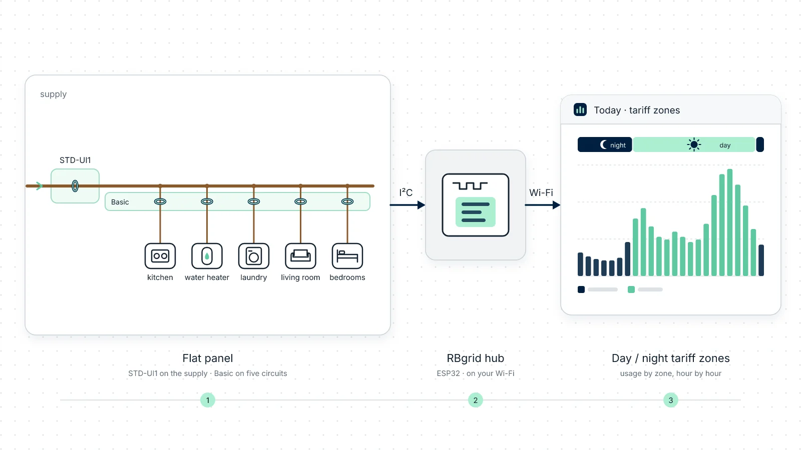
A two-room flat with an electric water heater, a kitchen and a washing machine. The electricity bill has a day rate and a cheaper night rate, and the question behind it is the usual one: where does the money go, and does it matter when things run?
This guide builds that flat on a real RBgrid hub: an rbAmp STD-UI1 meter measures the supply, a Basic module measures five circuits, and the app prices every circuit at the two-zone tariff. It's the same flat as the Flat site in the live demo, so you can look at the finished result before you build anything. The screenshots in this guide are from the demo and show demo data.
What you'll have at the end
- The power and cost of the whole flat right now, and of each circuit.
- Today and this month to date, at your day and night prices.
- History for every circuit, kept on the hub: by hour for 60 days, by day for about 13 months, by month for 3 years. You can download any of it as CSV.
- Notes from the app on where today's money went, what runs in the dearer zone, and how much the flat draws round the clock.
Already monitoring in Home Assistant? The hub can send every circuit's power and energy to Home Assistant over MQTT as well; your existing setup can stay as it is. The cost of each circuit at your tariff, the history views and the notes are in the RBgrid app. → A power meter for Home Assistant
What you need
| Hub | An ESP32-WROVER board with PSRAM and 16 MB flash, and its USB power supply. |
| Supply meter | One rbAmp STD-UI1, a precise energy meter, on the flat's supply. It comes with its own calibrated current sensor, in a 60 A or a 100 A kit: for a 40 A main breaker, the 60 A kit. It counts energy on the module, in both directions. |
| Circuit module | One rbAmp Basic UI5 for SCT-013: one voltage input and five current channels, one per circuit. |
| Clamps | Five voltage-output SCT-013 clamps for the circuits (below). The supply uses the STD-UI1's own sensor. |
| To set it up | A USB cable, a computer with Python (for esptool), your Wi-Fi password, and the short wires between the hub and the modules. |
The STD-UI1 is a precise energy meter: on the supply it gives exact metering of the whole flat, with the energy counters kept on the module itself, in both directions. The Basic module covers the circuits.
Choose each circuit clamp as the smallest rating at or above the circuit's breaker (see Choosing the clamp sizes).
| Circuit | Breaker | Clamp to buy |
|---|---|---|
| Kitchen | 16 A | SCT-013-020 |
| Water heater | 10 A | SCT-013-010 |
| Laundry | 10 A | SCT-013-010 |
| Living room | 10 A | SCT-013-010 |
| Bedrooms | 10 A | SCT-013-010 |
The demo flat has the same two modules; some of its clamps differ (30 A on several circuits, 5 A on the bedrooms). Build yours as above. Not sure which clamp you have? See Which SCT-013 do you have?
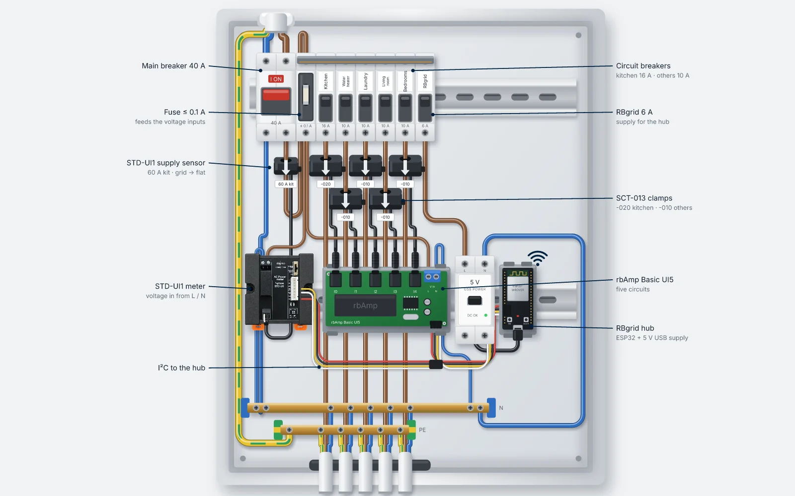
The drawing shows where the RBgrid parts go in the panel: the supply sensor under the main breaker, a clamp on each circuit, the two modules and the hub on the rail. Which protective devices your panel needs, and how they're arranged, is your electrician's.
Safety. For any work inside an electrical panel, call a qualified electrician.
Clamp one conductor only (L) per circuit, never the whole cable: the currents in L and N cancel out.
1. Wire, flash, connect
- Have the modules wired: both modules' voltage inputs to L and N through their fuses; the STD-UI1's sensor on the supply conductor; the five circuit clamps on the Basic module's I0–I4, each with the arrow pointing towards the load. A Basic module counts one direction only, so a clamp the wrong way round reads nothing. → the rbAmp wiring guide
- Connect only the STD-UI1 to the hub for now (power, GND, SDA, SCL), at its factory I²C address 0x50. → Quick start, step 1
- Flash the hub, join it to your Wi-Fi and open the app, at webapp.rbgrid.io or installed on the hub: follow the Quick start steps 2–4, then come back here.
A new hub makes the module at 0x50 your grid input by itself, the measurement of the whole flat, plus a voltage point. There's nothing to bind for it.
2. Run the setup wizard
The app opens with a banner, The hub still has its factory settings. Choose Set up →. → The setup wizard
- Security: set an API token and write it down.
- Site & time: scenario Home, a site name (the demo uses "Demo flat"), your time zone; check that the clock shows synchronized.
- Sensors: the grid input is already there. Leave the rest for step 3.
- Tariff: the quick form fits this flat. Enter the day price, switch on There is a night rate (23:00–07:00) and enter the night price. Leave Price as on the bill — incl. VAT on if your bill prices include VAT, and check the VAT, %: a new hub starts at 21 %. Leave the export price empty: a flat without solar exports nothing.
The demo uses Day 07:00–23:00 at 0.30 and Night 23:00–07:00 at 0.15 per kWh, VAT 20 %. Use your own bill's prices. Costs in RBgrid are energy-based: standing (monthly) charges aren't included. If your night hours differ from 23:00–07:00, set the zones in Tariffs instead (up to seven zones). → Tariffs
3. Add the circuit module and set up the circuits
The grid input. Open Points: the STD-UI1's card shows the grid input. A point is one named measurement. Open the input's Point setup and set:
- Input breaker, A: your main breaker (40 A here);
- Input limit, kW: what your supply allows. Without a contracted figure, use the breaker: 40 A × 230 V = 9.2 kW, as in the demo.
The STD-UI1's sensor is calibrated with the module at the factory, so there's no clamp model to choose.
The Basic module. Choose Add a module on the Points page and follow the dialog. Every module from the box answers at the same address, 0x50, so the app first moves the STD-UI1 to a free address. It keeps its points, history and settings. Then switch the hub off, connect the Basic module, switch on and scan. → Sensors and modules
The circuits. The Basic module's channels show as free sensors. Bind each one:
| Channel | Name | Role | Line rating | Breaker | Current sensor |
|---|---|---|---|---|---|
| I0 | Kitchen | Load | 3.68 kW | 16 A | SCT-013-020 |
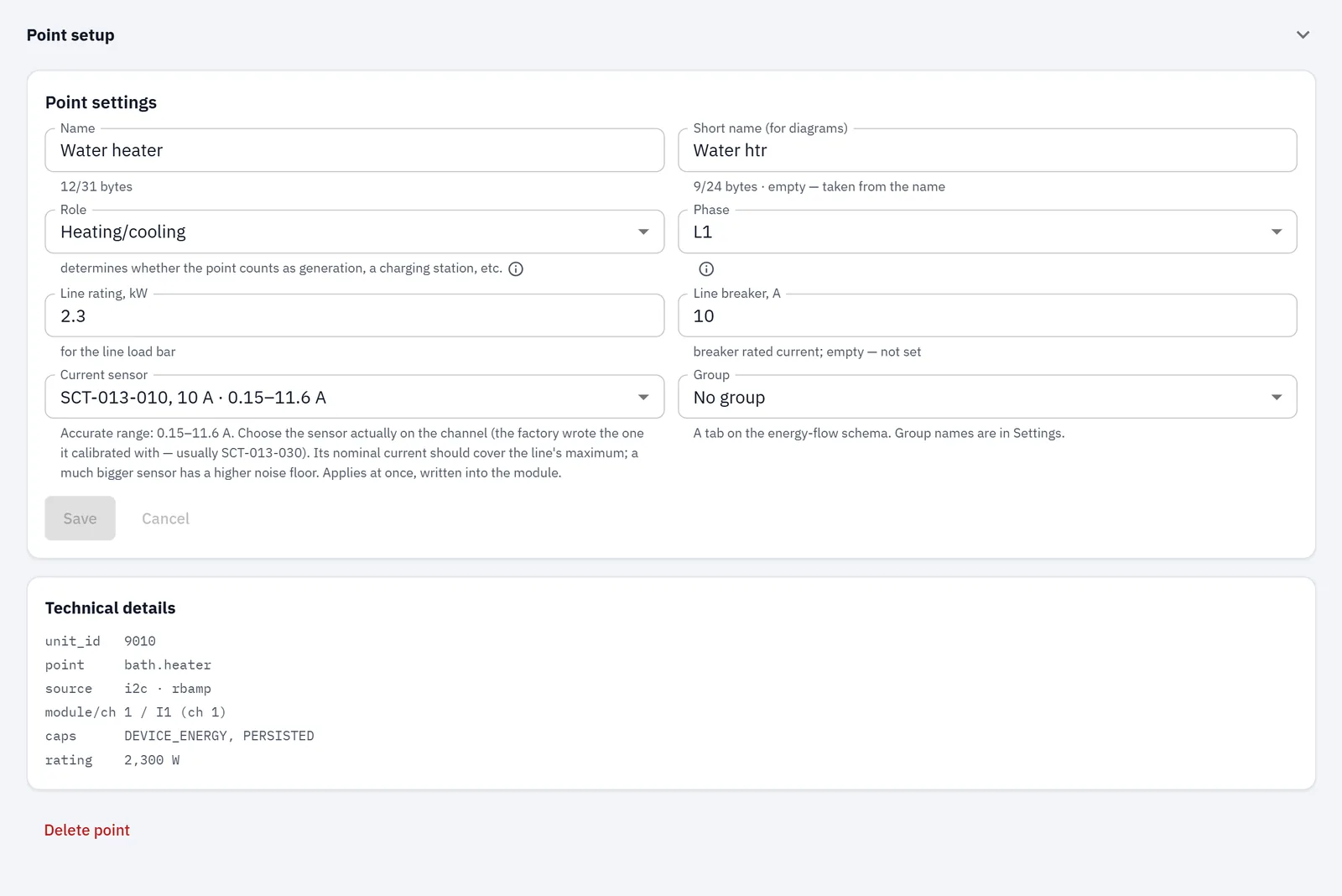
| I1 | Water heater | Heating/cooling | 2.3 kW | 10 A | SCT-013-010 |
| I2 | Laundry | Appliance | 2.3 kW | 10 A | SCT-013-010 |
| I3 | Living room | Load | 2.3 kW | 10 A | SCT-013-010 |
| I4 | Bedrooms | Load | 2.3 kW | 10 A | SCT-013-010 |
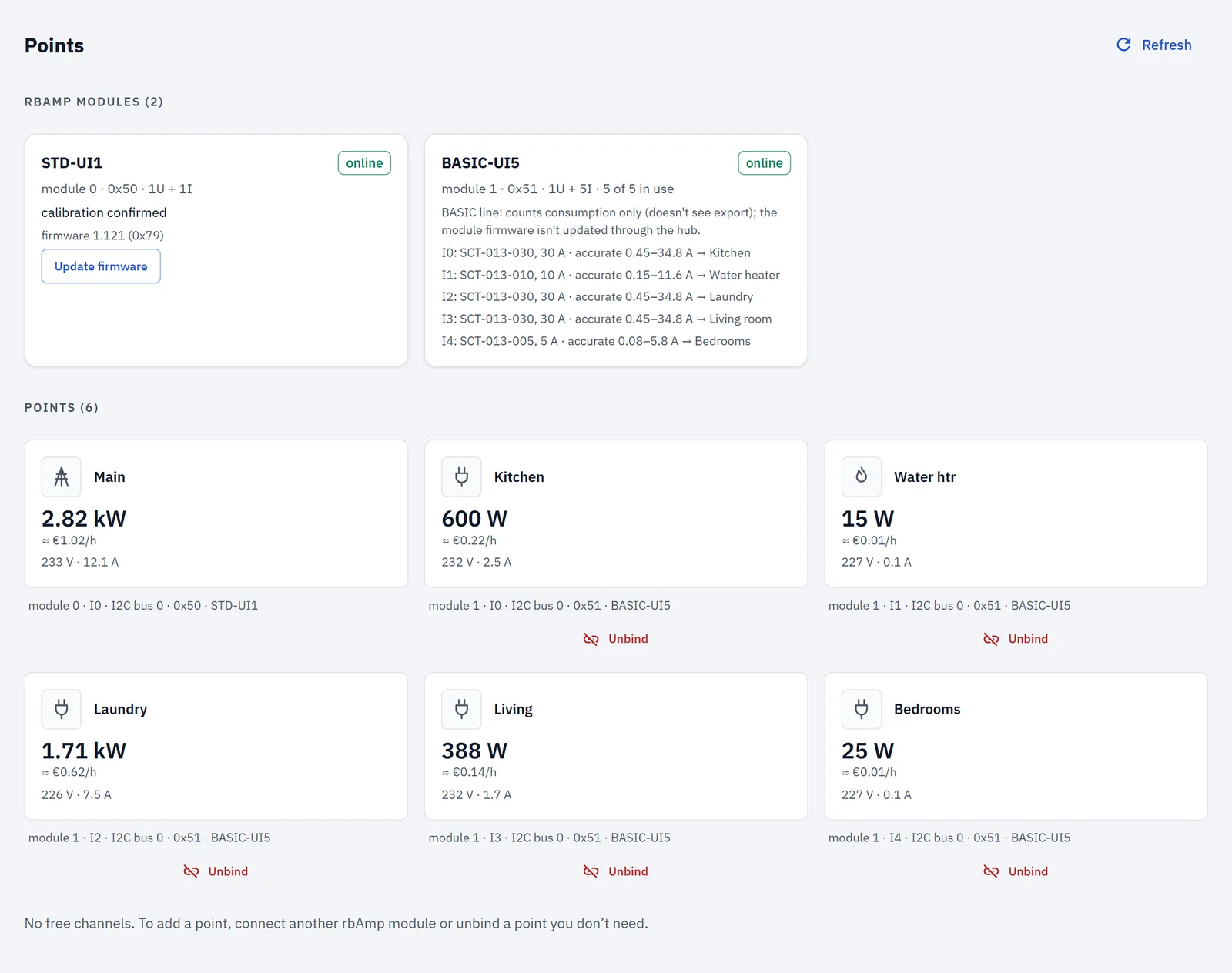
- Line rating is what the circuit's breaker allows (10 A × 230 V = 2.3 kW); the app uses it for the load bar on each line.
- Role Heating/cooling for the water heater keeps it out of the app's standby estimate, because it runs on its own schedule.
- Phase: L1 for all, or leave it unset: the flat is single-phase.
- Current sensor must match the clamp actually fitted. → Points
Group the rooms (optional). In Settings → Consumer groups, add a group "Rooms", then set Group to "Rooms" on the Living room and Bedrooms points. The Overview's flow card gets a "Rooms" tab.
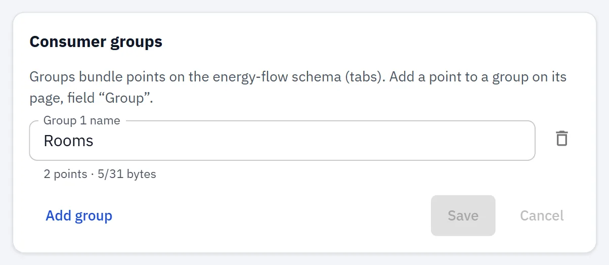
Restart the hub (Settings → Administration). A newly bound point shows live values at once and starts keeping history after the restart; nothing measured before is lost. The hub keeps history for up to 12 points; any more show live values only.
Check it: switch on a load you know, such as a kettle on the kitchen circuit. Its point should read about the kettle's rated power, and the grid input should rise by about the same amount.
4. What the app shows
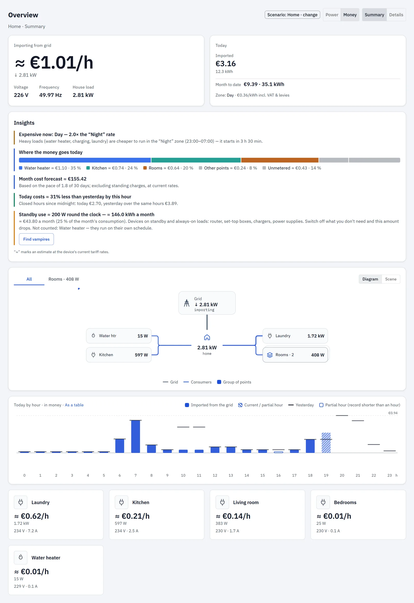
The Overview opens in money: what the flat costs per hour right now, today and this month to date, and the tariff zone in force. Below it, one tile per circuit. → The Overview
Insights turns the measurements and the tariff into short notes. In the demo flat, on an evening in the day zone, they read:
- Expensive now: Day — 2.0× the "Night" rate, with the hours of the night zone and how soon it starts;
- Where the money goes today: the three biggest circuits, the other points, and the unmetered rest (the grid input minus all metered circuits);
- Month cost forecast, from the pace so far, at current rates;
- Standby use ≈ … round the clock: the flat's night-time floor, taken from the quiet hours of the last nights, without heating and charging lines.
These are the app's estimates at your current rates, marked with ≈. Moving a load to the night zone is your call; RBgrid measures, it doesn't switch anything. → Insights
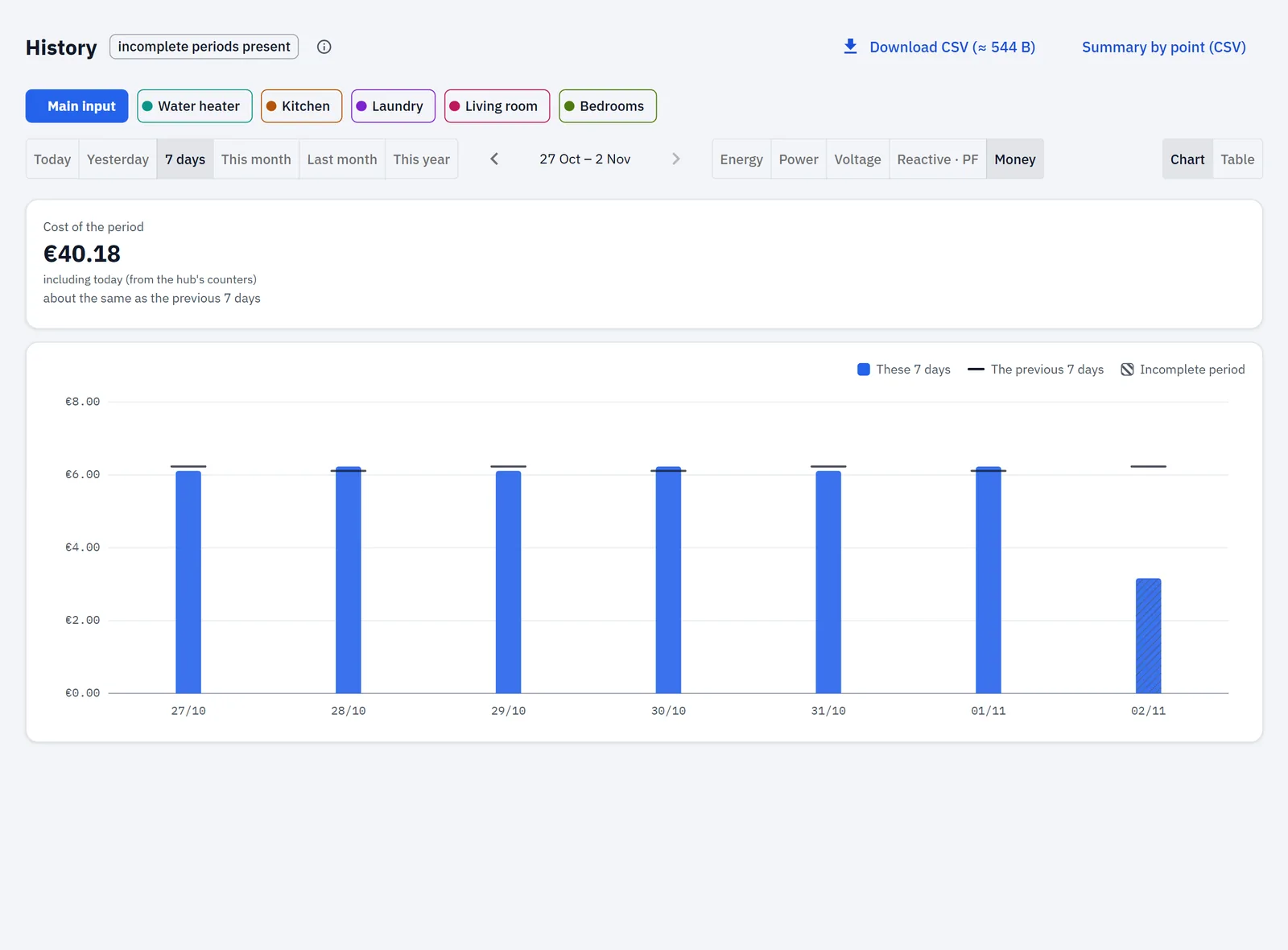
History shows each circuit by hour, day or month, in energy, power or money. In the demo flat, the water heater's two daily runs, mornings and evenings, stand out in the hourly view. Download CSV saves what you see. → History
Choosing the clamp sizes
A clamp has a range, and both ends matter:
- Too small: an SCT-013 clamp reads correctly up to about 116 % of its rating, then its readings are cut off and the circuit is under-counted. The hub flags sensor limit from about 104 % of the rating and clipping at about 116 %. A clamp rated at the circuit's breaker stays inside that range.
- Too big: on a Basic module, very small currents read as zero (below about 1.5 % of the clamp's rating), and energy below a matching threshold isn't counted. A 100 A clamp on a bedroom circuit would miss its small loads.
That's why the table matches each clamp to its breaker. → Points
Known issue in app 1.1.4: the point's settings check the breaker against a limit below the clamp's rating, so a 10 A clamp on a 10 A breaker shows "The line breaker 10 A is above the sensor's limit (9 A)…". The clamp reads correctly at its rating; the check will be corrected in an upcoming release.
Demo data vs your flat
- In the demo every day repeats the same pattern; only the laundry swaps between a morning and an evening run. Your history will look less tidy.
- The demo's day-to-day comparisons ("today costs … less than yesterday") come from that laundry swap, not from real behaviour.
- History starts when you set the hub up; data from other systems isn't imported.
- Your numbers depend on your circuits and prices; nothing in this guide promises a figure.
- Removing a point erases its history on the hub for good. Download its CSV first if you need it.
If something's wrong
- No sensors detected in Points: check the four wires to the hub, and that the first module is at 0x50. → Sensors and modules
- A circuit reads 0 while its load runs: the clamp may face the wrong way (the point says sensor reversed — not metered); turn it round.
- Sensor limit or clipping on a point: the circuit draws more than its clamp's rating; see Choosing the clamp sizes.
Next
- Add more circuits: add another Basic module; a hub takes up to eight modules. → Sensors and modules
- Refine the tariff: more zones, per-kWh fees. → Tariffs
- Send the data to Home Assistant. → A power meter for Home Assistant
- Look around the finished flat: demo.rbgrid.io, Flat